Electronic alarm clock with gas-discharge indicators and microcontrollers. Another clock with gas-discharge indicators Clock at 12
NiXIE. Clock diagram at 12
Retro watch on GRI IN-12
Circuit: yes (PIC16f886,PIC16F628)
Board: yes (Sprint-Layout)
Firmware: yes
Source: no
Description: yes
Features: no RTS, soft DC-DC high voltage.  The clock operates in a 24 hour format. There are alarm clock and temperature display functions. Power supply in the range 4.5...15V. Encoder control with button.
The design consists of two boards - a board with indicators and a control board. The boards are connected via PLS and PBS connectors. The connectors are soldered on the track side.

Enter the alarm clock settings by briefly pressing the encoder button (the minute and hour separator lights up without blinking). By rotating the encoder we adjust the signal time. Repeated short press (or 10 seconds of inactivity) – exit to clock mode (separator flashes). Allowing the alarm to go off is a long press (hold) until a signal appears: a short signal is disabled, a tone signal is enabled. After the alarm goes off, a tone sounds for 1 minute. The tone can be interrupted by pressing the encoder button.
The temperature is displayed from 25 to 30 seconds.
From 9:00 to 21:00 the clock emits a short hourly signal.
Accuracy of operation - approximately 1 second per day (tested in another project). The quartz should be tied (loaded) with recommended containers. Wash and dry the quartz installation site and adjacent lines. Connect the quartz body to the minus.

 Project archive. Primary source.
 Simple clock with retro lamps IN-12

Control the clock with three buttons – “increase”, “decrease” and “ok” (mode selection).
The clock operates in a 24-hour format. A short press on the “ok” button cycles through the modes: clock, alarm, brightness. There is an alarm clock. A long press on the “ok” button determines when the alarm clock is triggered: a short signal is disabled, a tone signal is switched on. In the clock, you can adjust the brightness of the lamps and, accordingly, the current consumption. Brightness adjustment within 0...99 levels. From 9:00 to 21:00 the clock emits a short hourly signal.
A method of combating the poisoning of lamp cathodes (or anti-poisoning) has been implemented. Before changing the minutes, all numbers in all lamps are quickly searched/
Some parts can be replaced:
Voltage stabilizer KR1158EN5A (TO-251) = 7805 (TO-220)
Field effect transistor STU6N62K3 (IPAK) = IRF840 (TO-220)
Inductance 1000 µH = 470 µH.
Capacitor 4.7 uF x 350V = 10 uF x 350V
Schottky diode 1N5817 = 1N5819 (not recommended).
There are many analogues to the installation components - almost any horizontal CR2032 battery holders, 6x6 mm clock buttons, piezo emitters with a diameter of up to 12 mm, any available panels for microcircuits.
To increase the accuracy of the watch, load 32768 Hz quartz with the recommended capacities. Wash the quartz installation site and adjacent lines with a solvent and dry. Connect the quartz body to the common negative.


 Display board converted to IN-14 from servoloshin.
 servoloshin says:
I modified the board to suit my needs: I thickened it in some places, added pads for backlight LEDs. I moved the top board under IN-14, it might be useful for someone, just connect it with wires there, the numbering has moved.
robocua.blogspot.com
VHF receiver with clock on IN-12

Circuit: yes (PIC16f876)
Board: yes (Sprint-Layout)
Firmware: yes
Source: no
Description: yes
Features: Indication of the received signal strength (RSSI) on a dial indicator.  The receiver with clock operates in the VHF FM range 76-108 MHz. Frequency setting in manual and automatic mode (auto search). Time is displayed in 24 format. Indication of the received signal strength (RSSI) on the dial indicator. Stereo amplifier 2x8 W. Stationary power supply 220V. This is a simple receiver with a mix of old and modern components. For indication, gas-discharge lamps of the IN-12B type are used (other lamps can also be used). The design allows you to easily configure everything (adjust) the operating mode by ear and eye.
Important! To operate the amplifier, you need a power source with a current of 1.5–2 A. For compactness, the RS-25-12 (Mean Well) power module is used, but due to the high cost, you can choose something else. The board provides a mounting location for the diode bridge for the case of using an iron transformer.
To power the lamps, a boost converter is assembled on the MC34063. Using a 5K trimmer resistor, we set the voltage at the output of the converter to 160-175V (for IN-12B lamps).
A variable resistor in the microammeter circuit regulates the current (the angle of deflection of the arrow). The microammeter can be for a different current (up to 1 mA). A microammeter may not be installed at all if the design does not fit into the housing.
The trimmer in the volume control circuit sets the maximum volume level (a very decent volume level). The variable resistor can be of a different value (+/-50%), but preferably with a linear characteristic (not logarithmic). Install the TDA7057AQ amplifier chip on the radiator.
Setting the clock. In manual mode, use the buttons to set the frequency to 108.1 MHz, then switch to automatic mode and use the buttons to set the time. After tuning, switch to manual mode to move away from the frequency of 108.1 MHz.
Most of the time the indicator shows the current time. From the 30th to the 35th second the current frequency is displayed. Indirectly, the brightness of the lamps (and current) can be adjusted using a trimming resistor in the voltage converter.

In our example, the G748 case (225x165x65mm) is used. Hole templates are attached in *.spl7 format. Buttons KM1-1 (PKN6-1), toggle switch MT1 (I have one toggle switch without a function; you can put it on power). Variable volume resistor S16KN1 and a knob for it 41026-1 (D45.1mm, 6mm hole with flat). I considered it inappropriate to install a pair of speakers in such a case, so I installed one JVC CS-J410X (it requires a case that is orders of magnitude larger and stronger) + the fan grille fits perfectly. Telescopic antenna with BNC connector AST-24 D7mm S7 150-650mm + mating part on the housing. 220V connector (male) to the AC-11 unit, 2 contacts, fastening with screws + standard cord.
 The clock receiver is assembled on two boards, which are connected by a ribbon cable.
  Please note that the display board has connector combs mounted on the track side. The control board, as well as the circuit, at first glance seem complex, but, in fact, all the components are in their place and are understandable. The board is made with a reserve for the future (remote control and temperature sensor), which are planned to be implemented later. In the proposed circuit, the microcontroller can be programmed in-circuit. The choice of microcontroller was made in favor of PIC16F876A, because it is more affordable for purchase and can be flashed with basic programmers (with available software). Upon request, I can recompile the firmware for the cheaper PIC16F886 (and it can be used without 4 MHz quartz).
 Original source
 Archive with firmware, board and hole templates.
Photos of the finished product from valerab (Radiocat):
Photo from Nikolay Yashkin (Nikolaj666 Radiokot).

robocua.blogspot.com
NiXIE: Transparent watch

Circuit: yes (ATtiny2313)
Fee: yes
Firmware: yes
Source: no
Description: yes
Features: implementation of the circuit and case from Ian. Scheme: 
Original diagram from *Trigger*:
I wanted to make a watch that would also serve as a beautiful night light. And this is what came out of it. It's based on the same *Trigger* circuit. I decided to make the body inlaid from transparent acrylic.
 The clock is made on two boards.

 In one part I milled out a recess for the display board.
  Pre-assembly. Thank God all the holes and grooves are calculated correctly, everything matches, we can continue to assemble.

Finished watch.


 By the way, for those who are planning to repeat my watch: first press MODE, wait 1 second (the separator lights up and stops blinking), now use the SET button to set the hours, press MODE, wait 1 second (the separator goes out), now use the SET button to set the minutes, press MODE , now for the version without rep. coefficient - the value will be written to the RTC, the dot will blink. for the version with coefficient. - the clock will go out and the previous coefficient will be displayed instead of minutes. in seconds, it can be changed with the SET button, now press MODE, the separator will flash, the clock will go...
 Case from valerab
Schematic, boards (in Deeptrace). Firmware. Case drawing from mms_ja.
robocua.blogspot.com
Clock on IN12 / Blog named after. BlackAlex / Collective blogs / Steampunker.ru
I’ve been itching for a long time to make a clock using NIXIE indicators. The payment is there, but it’s too stolen. Inspired by Ian's article steampunker.ru/blog/10810.html#cut A simple, accessible scheme. Based on the information provided, I ordered boards in China and away we go. I soldered 6 pieces, a pair on IN12. All watches are for gifts. The first for my father's birthday, I was in a hurry, not everything turned out as I wanted, as it should. The only tools are a jigsaw and a belt sander. I will expand my machine park.


The material used for the body was industrial merbau parquet. I just had the opportunity to buy such exotic wood inexpensively. Planks 15*20*200mm. I picked the ones that were close in color and off we went. The patterns were made in Corel. I drew a sketch in 3D MAX and selected the proportions.


I cut the clock panel out of 3mm plywood from a fruit box and covered it with wenge veneer. Unfortunately, the veneer was taken from the demonstration stand, it was overdried, it broke and crumbled badly. From now on, it will be necessary to pre-wet and glue the inside with gauze or a bandage.


the body was sanded and coated “hot” with homemade wax mastic. It feels very pleasant to the touch and is warm. Beautiful matte shine, natural smell of wood and wax.

I messed up a little with the glass. It was planned to be silicate, glued with optical glue. But the production time is 2-3 weeks. I ordered a part made of acrylic, but when bending it didn’t fit in size. I ordered 3 elements in reserve - they went into assembly. I glued the bottom with cyanoacrylic glue - it, like an infection, rose up the seam by capillary action and left marks on the glass. I had to redo it, and this was on the last day. It was not possible to make two nameplates from brass. The photoresist was stubbornly washed off from the material during development. Brass is etched very slowly in ferric chloride. In general, the technology did not win at once. We will explore further. This is what happened in the end.


If anyone is interested, there are “bare” boards, and there are ready-made, assembled ones with indicators.
steampunker.ru
NiXIE: KASHAK Nixie clock IN-14

Circuit: yes (ATmega8)
Board: yes (Sprint-Layout 6)
Firmware: yes
Source: yes
Description: yes
Peculiarities: ---  This article will focus on making original and unusual watches. Their uniqueness lies in the fact that the time is indicated using digital indicator lamps. A huge number of such lamps were once produced, both here and abroad. They were used in many devices, from watches to measuring equipment. But after the advent of LED indicators, the lamps gradually fell out of use. And so, thanks to the development of microprocessor technology, it became possible to create watches with a relatively simple circuit using digital indicator lamps. I think it would not be out of place to say that mainly two types of lamps were used: fluorescent and gas-discharge. The advantages of luminescent indicators include low operating voltage and the presence of several discharges in one lamp (although such examples are also found among gas-discharge indicators, but they are much more difficult to find). But all the advantages of this type of lamp are offset by one huge disadvantage - the presence of a phosphor, which burns out over time, and the glow dims or stops. For this reason, used lamps cannot be used. Gas discharge indicators are free from this drawback, because a gas discharge glows in them. Essentially, this type of lamp is a neon lamp with multiple cathodes. Thanks to this, the service life of gas-discharge indicators is much higher. In addition, both new and used lamps work equally well (and often used ones work better). However, there are some drawbacks; the operating voltage of gas-discharge indicators is more than 100 V. But solving the problem with voltage is much easier than with a burn-out phosphor. On the Internet, such watches are common under the name NIXIE CLOCK.
So, everything seems clear about the design features, now let’s start designing the circuit of our watch. Let's start by designing a high-voltage voltage source. There are two ways here. The first is to use a transformer with a secondary winding of 110-120 V. But such a transformer will either be too bulky, or you will have to wind it yourself, the prospect is so-so. Yes, and voltage regulation is problematic. The second way is to assemble a step up converter. Well, there will be more advantages here: firstly, it takes up little space, secondly, it has short-circuit protection, and thirdly, you can easily adjust the output voltage. In general, there is everything you need to be happy. I chose the second path, because... I had no desire to look for a transformer and winding wire, and I also wanted something miniature. It was decided to assemble the converter on MC34063, because I had experience working with her. The result is this diagram:

The next stage of development was the design of the lamp switching circuit. In principle, controlling lamps is no different from controlling seven-segment indicators, with the exception of high voltage. Those. It is enough to apply a positive voltage to the anode and connect the corresponding cathode to the negative supply. At this stage, it is necessary to solve two problems: matching the levels of the MK (5V) and lamps (170V), and switching the cathodes of the lamps (they are the numbers). After some time of thought and experimentation, the following circuit was created (smiled, because this has long been a standard anode switch circuit for GRIDs) to control the anodes of the lamps:

And controlling the cathodes is very easy; for this they came up with a special K155ID1 microcircuit. True, they have long been discontinued (in fact, it can still be ordered from a factory in Belarus, in large quantities), as well as lamps (homemade lamps have already appeared at foreign auctions), but buying them is not a problem. Those. to control the cathodes, you just need to connect them to the corresponding pins of the microcircuit and submit data in binary format to the input. Yes, I almost forgot, it is powered by 5V, well, a very convenient thing. It was decided to make the display dynamic because otherwise, you would have to install K155ID1 on each lamp, and there will be 6 of them. The general scheme turned out like this:

Under each lamp I installed a bright red LED, it’s more beautiful. The hardest part is over, all that remains is to develop a circuit for the “brain” of the watch. For this I chose the Mega8 microcontroller. Well, then everything is quite easy, we just take it and connect everything to it in the way that is convenient for us. As a result, the clock circuit included 3 buttons for control, a DS1307 real-time clock chip, a DS18B20 digital thermometer, and a pair of transistors for controlling the backlight. For convenience, we connect the anode keys to one port, in this case it is port C. When assembled, it looks like this:
There is a small error on the board, but it has been corrected in the attached board files. The connector for flashing the MK is soldered with wires; after flashing the device, it should be unsoldered.
And this is what it all looks like assembled:
 Now all that remains is to write the firmware for the microcontroller, which is what was done. The functionality is as follows: Display of time, date and temperature. When you briefly press the MENU button, the display mode changes. 1 mode - time only. 2 mode - time 2 minutes. date 10 sec. 3 mode - time 2 min. temperature 10 sec. 4 mode - time 2 min. date 10 sec. temperature 10 sec. When held, the time and date setting is activated, you can move through the settings by pressing the MENU button. The maximum number of DS18B20 sensors is 2. If the temperature is not needed, you can not set them at all; this will not affect the operation of the watch in any way. The sensor is not hot-pluggable. When you briefly press the UP button, the date is turned on for 2 seconds. When held, the backlight turns on/off. When you briefly press the DOWN button, the temperature turns on for 2 seconds. From 00:00 to 7:00, the brightness is reduced. The whole thing works like this:
Firmware sources are included with the project. The code contains comments so it will not be difficult to change the functionality. The program is written in Eclipse, but the code compiles without any changes in AVR Studio. The MK operates from an internal oscillator at a frequency of 8 MHz. Fuses are set like this:
 And in hexadecimal form it’s like this: HIGH: D9, LOW: D4 Also included are boards with corrected errors. This clock operates for a month. No problems were identified in the work. The LM7805 regulator and converter transistor are barely warm. The transformer heats up to 40 degrees, so if you plan to install the watch in a case without ventilation holes, you will have to use a higher power transformer. In my watch it provides a current of around 200mA. The accuracy of the movement is highly dependent on the quartz used at 32.768 KHz. It is not advisable to install quartz purchased in a store. The best results were shown by quartz from motherboards and mobile phones. In addition to the lamps used in my circuit, you can install any other gas-discharge indicators. To do this, you will have to change the board layout, and for some lamps the voltage of the boost converter and the resistors on the anodes. Attention: the device contains a high voltage source!!! The current is small, but quite noticeable!!! Therefore, you should be careful when working with the device!!!
 Photos of watches repeated by Appll:
Photo of the next modification of the watch:


Clock modifications for different lamps:
For 4 lamps, which seem to have a glitch, I’ll skip it.
A fascinating neon glow, somewhat similar to the glow of vacuum tubes, similar in appearance. All this gives a feeling of the past at the stage of development, knowledge and the beginning of the use of electricity, as far as one can imagine from books, films, illustrations. This is how I wrapped it up. But first things first.
Back to the past?
Retro(Also retro style; retro style from lat. Retro“back”, “turned to the past”, “retrospective”) - a rather abstract art-historical term used to describe various categories of ancient things that have some cultural and/or material value, and, as a rule, are not often found in modern everyday life with its deliberate practicality and desire to get rid of “extra” details. (Wikipedia).
Something like that. But progress did not and does not stand still. Everything is miniaturized and unified while increasing functionality. And this is where microcontrollers and other programmable integrated circuits (ICs) come to the rescue. You can, of course, use simpler devices to achieve greater authenticity of the manufactured product, but... this is a completely different topic for conversation.
This is all to say that it is not necessary to return to the possibilities of the past, but to use the available present. There are, of course, other implementation methods; here we consider a specific solution to the problem on a microcontroller (MK) manufactured by ATmega8.
External correspondence to the “ghosts” of the past depends entirely on the imagination, views, and tastes of the person making this retro-style device. Undoubtedly, someone likes other directions in design, then you have the cards in your hands.
What's the point?
The offered watches have the following functionality:
- Time display in HH:MM:SS format
- Option to show dividing points (for greater clarity)
- Ability to display the date in the format DD:MM:YY at the beginning of every hour (~10 sec)
- Forced date display
- Possibility of playing an hourly signal
- Setting up to 10 alarms at different times in HH:MM format
- Repeat the alarm signal (if not turned off) 5 minutes from the moment it goes off
- Changing the number switching effect (smooth switching)
- Save settings and continue timing when power is turned off
- Every 10 days of operation at 00:00:00 a two-minute cathode anti-poisoning mode is activated

After switching on, the clock will stand still; in order for it to go, you need to set the time.
Poking buttons
The clock is controlled by 4 buttons. Each press produces a beep
For configuration, 4 modes are used (without the “default” mode), which are switched cyclically (0 -> 1 -> 2 -> 3 -> 4 -> 0, “0” is used to bind to the program).
If no button is pressed for about 10 seconds, the watch goes into default mode. When you select the desired parameter to set it with the "NEXT" button, the corresponding value will flash, and when it is changed with the "SET" button, the dividing dots will light up. This means that the current value of at least one parameter has been changed and, if necessary, it must be saved by pressing the "SAVE" button, the dividing dots will go out. If you set invalid time or date values and try to save them with the "SAVE" button, the recording will not be made, as indicated by the burning dots.
Time setting: the required value is set; when setting seconds (both tens and units), they are reset to “0”. Then, at the right time, the entered values are saved.
Date setting: here the required value is simply set and saved.
Alarm setting: Hours and minutes are set, when changing the value in the position for tens of seconds, alarms are sequentially sorted (up to 10 alarms can be configured in total), in the position for units of seconds, the alarm clock is activated when setting “1”, and, accordingly, is deactivated by setting “0” (with firmware all alarms are set at 00:00 and turned off).
Additional settings: here each parameter is responsible for a slight change in functionality. The table shows the values of additional settings.
(when flashing all values are set to "0"). The melody for the alarm clock was made alone, “A grasshopper was sitting in the grass,” so to speak, as a test (I can’t guarantee that you’ll like it :)). When using a buzzer, it is not recommended to set a melody, as there will be a mess of sounds that “cut” the ear.
The firmware is written in C languages in the . The source code (with detailed, I think, comments) is attached. The printed circuit board design and circuit are made in . For those who do not know this tool, everything has been converted to PDF.
If there is time, perhaps something will be added to the firmware, but for everyday use, in my opinion, this functionality is enough. Or everyone can change and add what they need.
A short video of the clock working:
And a couple more pictures


Used materials:
1. Boost DC-DC converter
2.DS1307
3. A huge topic on watches at the GRI
Update
Updated firmware from 05/07/2019.
- Two display effects have been added - a smooth transition from one digit to another, changing a digit by brute force (configurable in the on/off item for the smooth change effect).
- Added analog temperature sensor type LM35 (you can use a similar type with a characteristic of 10 mV/°C). The sensor output is connected to the 26th leg of the MK. On the printed circuit board there is initially a slot for the connector. Temperature readings are displayed by pressing button 2(NEXT) in time display mode.
- Added night mode - reduced brightness from 22:00 to 6:00. (For those who did not have enough brightness in normal mode, the anode resistors of the indicators can be reduced to 1-2.2 kOhm).
- Due to some changes and optimizations in the firmware, the correct operation of the alarm clock (if anyone uses it at all) has not yet been verified. As planned, it should work like this: when setting the alarm, in the seconds position - 0 - off; 1,2,3,4,5,6,7 - by day; 8 - weekdays; 9 - all days.
The archive (Clock_firmware_7.05.2019.zip) with the firmware (sources will not be included) is attached below.
List of radioelements
| Designation | Type | Denomination | Quantity | Note | Shop | My notepad |
|---|---|---|---|---|---|---|
| U1 | Real Time Clock (RTC) | DS1307 | 1 | To notepad | ||
| U2 | Encoder, decoder | SN74141 | 1 | SN74141N or K155ID1 | To notepad | |
| U3 | MK AVR 8-bit | ATmega8A | 1 | ATmega8A-PU | To notepad | |
| U4 | Linear regulator | L7805AB | 1 | To notepad | ||
| U5 | DC/DC pulse converter | MC34063A | 1 | To notepad | ||
| Q1, Q3, Q6, Q8, Q10, Q12, Q15 | Bipolar transistor | KT940A | 7 | MPSA42, MPSA92, BF422 BF423 | To notepad | |
| Q2, Q4, Q7, Q9, Q11, Q13, Q16 | Bipolar transistor | KT3157A | 7 | To notepad | ||
| Q5 | Bipolar transistor | 2N5551 | 1 | To notepad | ||
| Q14 | MOSFET transistor | IRF740 | 1 | To notepad | ||
| D1-D6 | Rectifier diode | 1N4148 | 6 | To notepad | ||
| D7 | Rectifier diode | 1N4937 | 1 | To notepad | ||
| C1 | Capacitor | 0.047 µF | 1 | To notepad | ||
| C2, C3, C5, C6, C8, C10 | Capacitor | 0.1 µF | 6 | To notepad | ||
| C4 | 100 µF 25V | 1 | To notepad | |||
| C9 | Electrolytic capacitor | 10 µF 25V | 1 | To notepad | ||
| C11 | Electrolytic capacitor | 470 µF 25V | 1 | To notepad | ||
| C12 | Capacitor | 100 pF | 1 | To notepad | ||
| C13 | Capacitor | 470 pF | 1 | To notepad | ||
| C14 | Electrolytic capacitor | 4.7 µF 250V | 1 | To notepad | ||
| C15, C16 | Capacitor | 22 pF | 2 | To notepad | ||
| R2 | Resistor | 100 Ohm | 1 | To notepad | ||
| R3, R19, R28 | Resistor | 10 kOhm | 3 | To notepad | ||
| R4 | Resistor | 3 kOhm | 1 | To notepad | ||
| R5, R6, R10, R14, R20, R24, R29, R33 | Resistor | 4.7 kOhm | 8 | To notepad | ||
| R7, R11, R15, R21, R25, R30, R35 | Resistor | 33 kOhm | 7 | To notepad | ||
| R8, R12, R16, R22, R26, R31, R36 | Resistor | 100 kOhm | 7 | To notepad | ||
| R9, R13, R17, R23, R27, R32, R37 | Resistor | 470 kOhm | 7 | To notepad | ||
| R34 | Resistor |
Hi all. I want to tell you about my recent “craft,” namely a clock with gas-discharge indicators (GDI).
Gas discharge indicators have long since sunk into oblivion; personally, even the “newest” ones are older than me. GRIs were used mainly in watches and measuring instruments, later they were replaced by vacuum-luminescent indicators.
So what is a GRI lamp? This is a glass container (it's a lamp!) filled inside with neon with a small amount of mercury. Inside there are also electrodes curved in the form of numbers or signs. The interesting thing is that the symbols are located one after another, therefore, each symbol glows at its own depth. If there are cathodes, there must also be an anode! - he is one for all. So, in order to light a certain symbol in the indicator, you need to apply a voltage, and not a small one, between the anode and cathode of the corresponding symbol.
For reference, I would like to write how the glow occurs. When a high voltage is applied between the anode and cathode, the gas in the lamp, which was previously neutral, begins to ionize (i.e., a positive ion and electron are formed from the neutral atom). The resulting positive ions begin to move towards the cathode, and the released electrons begin to move towards the anode. In this case, the electrons “along the way” additionally ionize the gas atoms they collide with. As a result, an avalanche-like ionization process occurs and an electric current appears in the lamp (glow discharge). So now the most interesting thing, besides the ionization process, i.e. formation of a positive ion and electron, there is also a reverse process, called recombination. When a positive ion and an electron “turn” back into one! In this case, energy is released in the form of a glow, which we observe.
Now directly to the clock. I used IN-12A lamps. They have a not quite classic lamp shape and contain symbols 0-9.
I bought a fair amount of lamps that were not used!
So to speak, so that there is enough for everyone!
It was interesting to make a miniature device. The end result is a fairly compact piece.
The case was cut on a laser machine from black acrylic according to a 3D model, which I made based on printed circuit boards:


Device diagram.
The clock consists of two boards. The first board contains four IN-12A lamps, a K155ID1 decoder and optocouplers to control the lamp anodes.

The board also has inputs for connecting power, controlling optocouplers and a decoder.
The second board is the brain of the clock. It contains a microcontroller, a real-time clock, a 9V to 12V conversion unit, a 9V to 5V conversion unit, two control buttons, a buzzer and the outputs of all signal wires that match the display board. The real-time clock has a backup battery, which prevents time loss when the main power is turned off. Power is supplied from a 220V-9V unit (200mA is sufficient).


These boards are connected using a pin connector, but not by insertion, but by soldering!


The whole thing comes together this way. First, a long screw M3*40. A tube from a 4mm air hose fits onto this screw (it is dense and suitable for holding printed circuit boards, I use it very often). Then there is a stand between the printed circuit boards (printed on a 3D printer) and then a brass through nut tightens it all. And the back wall will also be fastened with M3 bolts to through brass nuts.


During assembly, this unpleasant feature became clear. I wrote the firmware, but the clock refused to work, the lamps flickered in an incomprehensible order. The problem was solved by installing an additional capacitor between +5V and ground right next to the microcontroller. You can see it in the photo above (installed it in the programming connector).
I am attaching project files in EagleCAD and firmware in CodeVisionAVR. You can upgrade if necessary for your own purposes)))
Firmware for the watch is done quite simply without any bells and whistles! Just a watch. Two control buttons. One button is “mode”, the second is “settings”. By pressing the “mode” button for the first time, only the numbers responsible for the hours are displayed; if you press “settings” in this mode, the hours will begin to increase (when they reach 23 they are reset to 00). If you click on “mode” again, only the minutes will be displayed. Accordingly, if you click “setup” in this mode, the minutes will also increase in a “circular” order. When you click on “mode” again, both hours and minutes are displayed. When changing the hours and minutes, the seconds are reset to zero.
Good afternoon:).
“Maybe make a clock on them?” - I asked myself this quite predictable question, having accidentally stumbled upon IN-12B gas-discharge indicators in one of the dusty boxes. And he also answered himself: “of course!” I have long wanted to collect something just for fun, “for the soul”, and a luminous watch is perfect for this :)
Attention: I'm slow: I rarely write here, most often when I want to take time off from work)). And everything new and interesting, invariably fresh, immediately ends up on Instagram. Click HERE, go to my account and subscribe :) I will always be very glad to see you! Enjoy reading:)
However, it is still unclear how things will go. The project itself is not complicated, but it is “for myself”, which means there will always be something more necessary, urgent, important.... I will tell you about all the progress with photo reports just like this one. I will not dwell in detail on the technical side of the matter. If you have any questions, ask, I will be happy to answer :).
And it all started with them:

Gas-discharge indicators IN-12B. Capable of displaying 10 digits from 0 to 9 and, it seems, a dot. “It seems” - because I never checked it :).
Managing the indicators is very simple. A voltage of 150 - 170 V is applied to the common anode of the lamp. And the cathode of the digit that needs to be “ignited” is connected to the minus of the source. That's all!

There are two obvious difficulties:
1. You need a high voltage source (150 - 170 V).
2. You need keys to control high-voltage signals on the cathodes of the indicators.
The first problem was temporarily solved by unearthing a mock-up of a pulse boost stabilizer in a box with prototypes. I assembled it for experiments with tube circuits, but never put it into practice.
Note: I will definitely provide a diagram of the source in the next post.
There were also no difficulties with the keys: I decided to install MPSA44 high-voltage transistors. They have been lying idle for a long time and are waiting in the wings. Then maybe I'll replace them with something smaller.
Note: You can also use specialized decryptors - K155ID1.
Connecting is simple:

Each digit is controlled by its own transistor. And this is how it looks on the layout.

I like these multi-colored wires - very convenient and beautiful:)

By the way, their female connectors fit perfectly onto the legs of the gas-discharge indicator:

After everything became clear with the control of the indicator, it was time to think about the “brains” of the watch. Maybe, to look smarter, you should choose a serious controller, and use professional development and debugging tools... Or go even further and use an FPGA. But I decided to risk the criticism of professional programmers and use ARDUINO. A simple development environment and simple hardware are exactly what you need for a simple and undemanding project in terms of speed and resources :).
The hardware is cheap: a clone of the ProMini board with an ATMega328 controller on board and a USB-UART converter. And for now, nothing more is needed:

The MK module was placed on the same breadboard and connected to the control transistors:

A little about dynamic display
I have a microcontroller, ten transistors it controls, and one indicator. Everything is fine, just not enough indicators for the watch :). We need three more. But before adding them, I decided to figure out how best to do this.
Putting ten transistors on each indicator is a bad idea. Firstly, it is expensive, secondly, it is bulky and thirdly, the controller simply does not have enough legs to control them (40 pieces will be needed).
It is better to organize dynamic indication, using ten transistors to control all indicators in turn, and selecting the desired indicator by applying voltage to its anode.
This technique works great with LED indicators, but will it also be effective with HID indicators? I don't know. The switching of indicators must occur very quickly, and suddenly during this time the discharge will not have time to ignite? This is what you need to check before moving on.
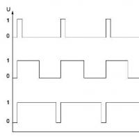
The existing indicator is enough for us to do this. A very simple program will display numbers on the indicator - imitate the dynamic mode: it will light the indicator for 5 ms, and then completely turn off for 15 ms (this is the time that in the dynamic mode it will take to light the remaining three indicators). And then it will light again, etc. ...
What came of it - in the video:
Everything is fine! Although the indicator is off most of the time, it is not noticeable. By the way, if you slightly change the on/off frequency, the associated flicker, still invisible to the eye, will become clearly visible in the video:
Conclusion: dynamic display works. Now you can safely connect the missing indicators and the anode voltage control circuit. But more on that next time :)
A little about functionality. They contain:
- date indication (year, month, day);
- time indication (hours, minutes, seconds);
- indication of days of the week;
- alarm;
- correction mode indication;
- “Alarm set” indication.
Power is supplied from a 12 V switching power supply. 0.3 A. Small and light. Something like this: 
The idea to power the device from a 12 V source is due to two reasons:
- Eliminates network bulky transformer
- For security.
In the circuit itself, a DC-DC Step-Down converter was implemented to power the controller, and a Step-Up converter to power the anodes. Both converters used MC34063. In my opinion, these are wonderful microcircuits, although they have been produced for a very long time.
The circuits of these converters are not original and were taken from datasheets for these microcircuits. 
And here, in fact, is the clock diagram: 
Assembled like this: 

Some of you may reproach me: “Why didn’t he make a dynamic display. This would significantly reduce the number of chips." And they will probably be right.
The reason is quite banal. Mother laziness. The fact is that indicators were made much earlier. This is a board with two IN12 and two K155ID1. I couldn’t find the socket under IN12, I had to solder it. And I was too lazy to unsolder. And there was no shortage of ID1 and IR22. And to be honest, when making this watch the emphasis was not on the circuit design.
IN12 was used to indicate the time, and to indicate the days of the week I used neon lights, which I tore out from ancient tube TVs. They stood there in the program selection blocks, if I’m not mistaken, they were INS-1.
In case of power failure, the watch has an emergency source. The indicators go out, but the clock continues to work.
Back cover: 
Front view: 
These are the nameplates: 
The heart of the watch is the Atmel ATMega32 microcontroller. Clocked by 4 MHz quartz. To clock the clock logic, I used a 32.768 KHz clock quartz.
The program was not particularly difficult.
First of all, I implemented the clock and calendar logic. Everything is simple here - I count the second impulses. I counted 60 - increased the minute and so on. The number of days in months is known, except for February, depending on the year. Using the formula, I determine the leap year. I also calculate the day of the week using the formula. At the same time, I check the alarm clock, otherwise I suddenly need to ring the bells. And I immediately display everything on indicators.
All these operations take up little processor time, so I poll the buttons for the rest of the time. There are four of them: UP, DOWN, MODE/ENTER, ALARM.
Using the UP and DOWN buttons in setup mode, I increase or decrease the parameter being adjusted. In normal mode, any of them switches the display to date display mode (4 seconds).
MODE/ENTER – enters the clock into time and date setting mode. All changes are applied with the same button.
ALARM – sets an alarm, or turns it off if the alarm rings or you just want to turn it off in advance.
A little protection from the “fool” - it cannot be set manually, for example, April 31, June 31, February 29 in a non-leap year, etc. But then I cheated a little - the year can only be set from 2000 to 2099 (there are two familiar places on the indicators), so it seemed that it should be enough. Although in the code the year is counted in full and, theoretically, the clock can count up to 2^16 years, it is not difficult to change this.
Separately, I implemented the ringing of bells. I made a kind of editor, that is, the melody itself is recorded in the form of durations (hit, release) for each cup. For what? Don't know. Still, he rings all the “melodies” like “Ding-Dong” :).
I wrote everything in Atmel Studio 6 in assembler.
Code available at